
There are three possible shim points along the powertrain:
1) the flat pump plate (which the impeller housing assembly bolts to);

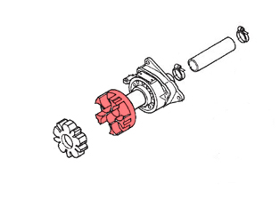
2) the bearing housing (which is attached to the coupler, highlighted in pink);
3) the four feet at the engine corners (only one is shown in the next picture).

There is also a "stopper" under the engine near the magneto that could require shimming as well. You may also find shims between the case and the feet (one bolt per), but I opted to not unbolt the feet from the cases. I would highly advise against ever messing with these as the bottom-most bolts (two bolts per foot) will maintain alignment much better and allow you to slide the engine easily.
There are three types of shims: 1) small, very thin horseshoe-shaped shims for the pump plate and bearing housing; 2) large plate shims about 3/32" thick for under the feet; 3) medium, nearly-square ~3/32" plates for under the stopper. I suppose stainless steel fender washers would be a good alternative to the horseshoe shims in a pinch. Not knowing what to expect going in, I ordered four spare horseshoe shims but only one each of the foot and stopper plates. I instead ordered some aluminum plate in 3/32" and 3/16" so I could cut some of my own if needed ...and I ended up cutting a bunch.
THE PUMP PLATE:
Do not attempt to align the pump plate or the bearing housing with the rubber hose still attached to the back of the bearing housing that allows the impeller shaft to pass through the hull - it will throw off alignment. Once you figure out the shims on the bearing housing, re-attach the hose and then do the final bolt-down before moving on to aligning the engine. The hose is indicated with red in the following picture.

The coupler needs to be inline all the way through to the impeller with no deflection of the shaft, so we'll first use the bearing housing as our guide to get the pump plate square. Install and torque the pump plate (I torqued these to 18ft-lbs) to the hull. You're going to need a helper reaching inside to hold a box wrench onto the pump plate nuts so you can tighten the bolts from the outside (especially when you seal this later and the silicone has a 5-10min working time). Mount the impeller housing/shaft assembly to the plate.
From inside the boat, slide the bearing housing with the coupler shaft onto the impeller shaft. Fully engage the bearing housing into the splines of the impeller shaft, press it against the engine wall and let go. If the bolt holes in the bearing housing line up with the holes on the engine wall (meaning you can easily slide the bolts through without touching the housing), the pump plate is correct and you can move on to shimming the bearing housing. If you have to adjust/push the bearing housing with one hand so you can get the bolts to pass with the other hand, the pump plate needs to be shimmed. Unbolt, shim, re-torque, and check again. Having the engines out so you can look directly at the holes will make knowing which corner(s) of the pump plate will need shims easier. Use the horseshoe-shaped shims placed between the plate and the gelcoat. Do not add silicone yet - sealing the pump plate to the hull is the last step.
THE BEARING HOUSING:
Again, if the bolts pass easily (nuts are not added yet) through the engine wall AND all three corners are flush to the wall without you touching the assembly, the bearing housing is properly aligned with the pump plate. If there are gaps at one or two corners, they will need to be shimmed with the horseshoe-shaped shims. Press on the corner making contact and start sliding in shim(s) to fill the gaps. If you've got it lined up, pull it and add the rubber hose (marked red in the last picture above) that joins it to the hull fitting. Remount and re-bolt the bearing housing in with the shims in place - I think I torqued these three bolts to 10ft-lbs.
THE ENGINE:
This is the most time-consuming/tedious part of the project. I ended up spending a lot of time getting one engine aligned, moved onto the next one only to realize the first one could've been better ...so I did one of them twice to make sure they were both perfect. You're going to need some way to relieve the weight on the feet so you can get the bolts in and out easily (they need to be removed a few times). You can do this with an automobile engine leveler on a pulley above the boat, connected to a winch like I did. Or you can simply attach ropes/chains to the engine hangers and have a partner pull on them to alleviate the tension on the bolts when you need to remove them. I made it even easier on myself by running the bolts through a die and re-tapping the holes prior to placing the engines back in the engine bay. I also had the engine hatch off, which made taking measurements at the coupler easy.
Aligning the engine comes down to aligning the engine-side coupler to the impeller-side coupler. You will need to leave the rubber coupler damper (looks like an asterisk) out for now. If you leave the damper in, it will bind and give you incorrect measurements, plus it will put stress on the engine bay wall at the bearing housing.
My starting point was with the old shims back where they were before I had pulled the engine. Then I threaded the eight bolts about halfway on all four feet. Again, relieving the weight will make it easier to get them in/out and you'll avoid cross-threading, which will cause a nightmare I would not want to experience. The bolts just have to be in (they don't need to be tight) to take the measurements, otherwise the weight will cause the feet to splay out and alignment will be off when you do your final bolt-in. You're going to be adding/removing shims and rechecking the tolerance at the couplers repeatedly.
I used one of the "stopper" shims as my straight edge to check the coupler alignment. Basically, place a straight edge on one coupler half and use a feeler gauge to measure the gap from that edge to the other coupler half. It should be no more than 0.50mm. I measured the gaps at about 12, 3, and 9 o'clock around the coupler each time. If any one is greater than 0.50mm, shims need to be added (or removed) somewhere. I'd say you really want to aim for under 0.35mm to get it perfect.

Finding the right combination of shims can quickly become frustrating. After a while, I started making it a little easier on myself by using the smaller "stopper" shims I had. I would lift the engine slightly with the bolts still halfway threaded and slide the stopper shim(s) in, which would give me a quick but accurate reading. Once I found what worked, I would then swap in the proper foot shim and double-check the tolerance - this saved my fingers some pain.
The truly frustrating aspect (aside from hurting yourself as you lean your skeleton over sharp corners to see the measurements) comes with trying to figure out in your head which foot needs shimmed to accomplish a specific direction at the coupler. What worked for me was to shim the aft feet to raise/lower the engine-side coupler and use the bow feet to get it to move left/right. This got me in the ballpark quickly, then I could fine tune it by adding a shim here or there until it finally got within tolerance. I think a lot of it was dumb luck and patience. The gap between the two coupler halves needs to be 2-4mm. I stacked two of the stopper shims and used them as a feeler gauge for this: if the stack didn't fit, I was good to go.
Once the coupler halves are aligned with the correct combination of shims, you'll have to remove all the bolts and slide the engine towards the bow so you can insert the rubber damper. Once in, slide the engine back into place and thread the bolts back in about halfway. re-check your measurement one last time. here is when you know you've gotten it perfect: the damper inside the coupler very easily moves around inside the two halves. You can't get any better than zero binding! When I got this on the second engine, I knew I had to go back and redo the first. Wait to tighten the bolts of the feet until the "stopper" is shimmed.
THE STOPPER:
The stopper doesn't actually make contact. It seems to be there to allow the engine to bounce, but not bounce too far. A fellow owner took a measurement for me since there is no spec in the manual. His stopper had a gap of 0.35" ...so somewhere around 8-9mm between the stopper rubber and the bottom of the case seemed right. To find the measurement, I slid the unbolted stopper where it needed to be and inserted as many stopper shims into the gap as would fit. With the stack now in my hand, I measured the thickness of the entire stack and removed shims until the stack measured about 8mm. The shims I took off that stack to get it down to 8mm was what I placed under the stopper. And yes, you need to have additional joints in your forearm to get these bolts in - they are tough! Add some Loctite. I used a short 10mm box wrench to make quarter turns to eventually get them down. If you can't bend your arm around a corner, you might have to lift the engine up.
FINALLY:
If everything is lined up, do a final bolt-in on the feet. Do one foot at a time by removing the bolts, adding some Loctite, and snugging them down good. I didn't find a torque spec anywhere, but I would guess it's got to be around 18-25ft-lbs. these bolts have lock washers on them, so it shouldn't be that crucial to get an accurate/high torque. Now go back and remove the pump and the pump plate. Get a friend, add gobs of silicone to the back of the pump plate, and re-bolt everything back up to specs.
You do not need to use 3M 4200 or 5200 when sealing the pump plate to the hull - Yamaha certainly did not find it necessary to use an equivalent. I used 3M Marine Grade Clear with no issues.